







AI-Powered Drone Inspection System for Infrastructure

We design and deploy artificial intelligence systems: from prototype to production-ready solutions. Our team combines expertise in machine learning, data engineering and MLOps to make AI work not in the lab, but in real business.
Showing 1 of 1All 1564 services
AI-Powered Drone Inspection System for Infrastructure
Complex
~2-4 weeks
Frequently Asked Questions

AI Development Areas

AI Solution Development Stages

Latest works

  • image_website-b2b-advance_0.webp
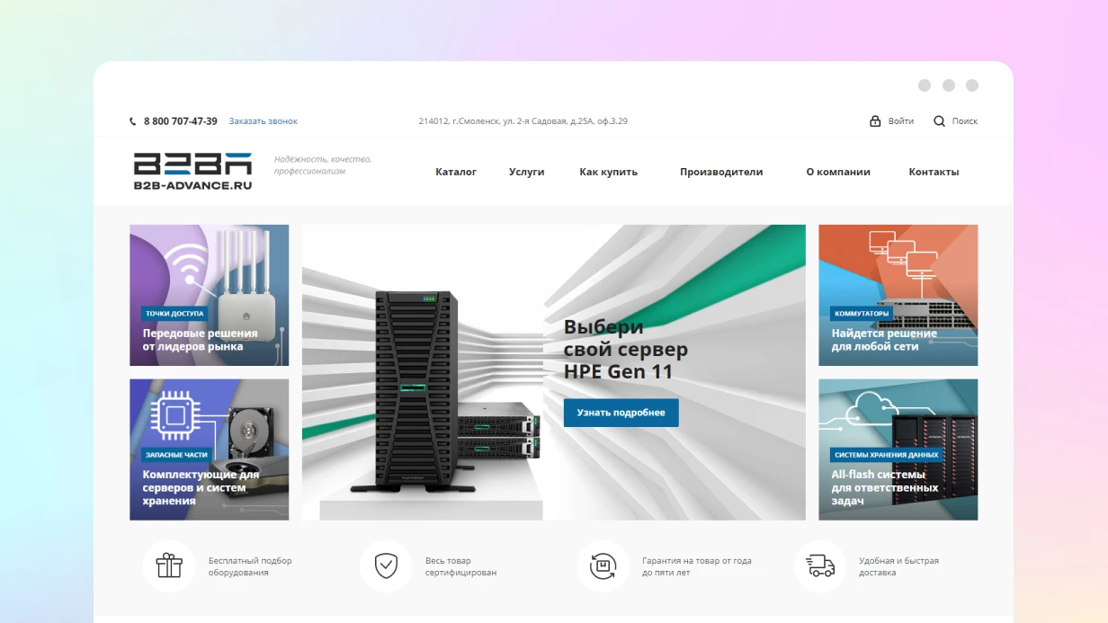
    B2B ADVANCE company website development
    1361
  • image_web-applications_feedme_466_0.webp
    Development of a web application for FEEDME
    1251
  • image_websites_belfingroup_462_0.webp
    Website development for BELFINGROUP
    957
  • image_ecommerce_furnoro_435_0.webp
    Development of an online store for the company FURNORO
    1189
  • image_logo-advance_0.webp
    B2B Advance company logo design
    646
  • image_crm_enviok_479_0.webp
    Development of a web application for Enviok
    929

Inspecting high-voltage power lines, bridges, oil pipelines, and wind turbines typically takes days of manual work by industrial climbers or requires equipment shutdown. A drone with AI analytics covers the same route in hours and detects defects that humans often miss during a quick visual check. We have been developing such systems for several years and have completed 15+ projects on automation of inspections for industrial clients. In this article, we break down how a real defect detection system works — from image capture to report.

Typical inspection tasks

Object Defects detected Method
Power lines, towers Corrosion, tower lean, broken wire Segmentation + anomaly detection
Wind turbine blades Cracks, delamination, ice buildup High-res defect detection
Bridges, overpasses Cracks, spalling, rebar corrosion Crack detection + classification
Oil pipeline Dents, corrosion spots, leaks RGB + thermal camera
Building roof Leaks, thermal anomalies Thermal camera

How does defect detection on images work?

The basic method is semantic segmentation of cracks on RGB images. We use the UNet++ architecture with an EfficientNet-B4 encoder — it provides pixel-level accuracy and is robust to noise. The model is trained on labeled data (crack masks) and outputs a binary map, from which the area and length of the defect are calculated. The detector code:

import torch
import numpy as np
from PIL import Image
from torchvision import transforms
import segmentation_models_pytorch as smp

class InfrastructureDefectDetector:
    def __init__(self, model_path: str, task: str = 'crack'):
        # For cracks — segmentation task (pixel-level accuracy)
        # UNet++ with EfficientNet-B4 encoder = good trade-off
        self.model = smp.UnetPlusPlus(
            encoder_name='efficientnet-b4',
            encoder_weights=None,  # load our own weights
            in_channels=3,
            classes=1,
            activation='sigmoid'
        )
        checkpoint = torch.load(model_path, map_location='cpu')
        self.model.load_state_dict(checkpoint['model_state_dict'])
        self.model.eval()

        self.transform = transforms.Compose([
            transforms.Resize((512, 512)),
            transforms.ToTensor(),
            transforms.Normalize([0.485, 0.456, 0.406],
                                  [0.229, 0.224, 0.225])
        ])
        self.task = task

    @torch.no_grad()
    def detect(self, image: np.ndarray,
               threshold: float = 0.5) -> dict:
        img_pil = Image.fromarray(image)
        tensor = self.transform(img_pil).unsqueeze(0)

        pred = self.model(tensor)[0, 0].numpy()  # (H, W)
        mask = (pred > threshold).astype(np.uint8)

        # Mask analysis
        crack_pixels = int(mask.sum())
        total_pixels = mask.size
        crack_ratio = crack_pixels / total_pixels

        # Crack contours
        contours, _ = cv2.findContours(mask, cv2.RETR_EXTERNAL,
                                        cv2.CHAIN_APPROX_SIMPLE)
        crack_regions = []
        for cnt in contours:
            area = cv2.contourArea(cnt)
            if area < 50:  # noise filter
                continue
            x, y, w, h = cv2.boundingRect(cnt)
            length = cv2.arcLength(cnt, False)
            crack_regions.append({
                'bbox': [x, y, x+w, y+h],
                'area_px': int(area),
                'length_px': float(length),
                'severity': self._classify_severity(area, length)
            })

        return {
            'defect_ratio': crack_ratio,
            'crack_regions': crack_regions,
            'severity': 'HIGH' if crack_ratio > 0.02 else
                        'MEDIUM' if crack_ratio > 0.005 else 'LOW',
            'raw_mask': mask
        }

    def _classify_severity(self, area: float,
                             length: float) -> str:
        if length > 200 or area > 500:
            return 'CRITICAL'
        elif length > 80 or area > 100:
            return 'HIGH'
        return 'MEDIUM'

The severity threshold is configurable according to enterprise standards. Cracks longer than 200 pixels are marked as critical — the object requires unscheduled repair.

Training technical details

For each model we apply augmentations: random rotation, brightness jitter, mosaic. We use AdamW optimizer with a learning rate of 1e-4 and cosine annealing. Validation uses IoU and F1-score. After training, we export to ONNX for inference on Jetson.

Why is thermal imaging indispensable?

Corrosion and leaks are often invisible in RGB images but show temperature anomalies. A thermal camera detects overheating of power line contacts (short circuit) or cold zones on roofs (insulation leak). Our thermal frame analyzer looks for areas where temperature deviates from the mean by more than 3 sigma:

class ThermalInspector:
    def __init__(self, baseline_temp: float = 20.0):
        self.baseline = baseline_temp

    def analyze(self, thermal_frame: np.ndarray) -> list[dict]:
        """
        thermal_frame: temperature matrix in °C
        Look for abnormally hot (short circuit, friction) and cold
        (leaks, missing insulation) zones.
        """
        anomalies = []

        # Frame statistics
        mean_t = float(np.mean(thermal_frame))
        std_t = float(np.std(thermal_frame))

        # Anomalies: > mean + 3*std (hot) or < mean - 2*std (cold)
        hot_mask = (thermal_frame > mean_t + 3 * std_t).astype(np.uint8)
        cold_mask = (thermal_frame < mean_t - 2 * std_t).astype(np.uint8)

        for mask_type, mask in [('hot', hot_mask), ('cold', cold_mask)]:
            contours, _ = cv2.findContours(mask, cv2.RETR_EXTERNAL,
                                            cv2.CHAIN_APPROX_SIMPLE)
            for cnt in contours:
                if cv2.contourArea(cnt) < 20:
                    continue
                x, y, w, h = cv2.boundingRect(cnt)
                roi_temps = thermal_frame[y:y+h, x:x+w]
                anomalies.append({
                    'type': mask_type,
                    'bbox': [x, y, x+w, y+h],
                    'max_temp': float(roi_temps.max()),
                    'min_temp': float(roi_temps.min()),
                    'delta': float(abs(roi_temps.mean() - mean_t))
                })

        return anomalies

This approach detects defects at an early stage before they lead to failure. According to Thermography (Wikipedia), thermal inspection is widely used for predictive maintenance.

Photogrammetry and 3D model: when is it needed?

For detailed analysis of cracks and deformations, we build a 3D model from a series of overlapping images. Tools: Agisoft Metashape (commercial), OpenDroneMap (open-source), COLMAP. Recommended overlap — 80% front-side, GSD — 1–3 mm/pixel. With a drone equipped with a Sony RX1R II camera (42 MP), you can get a GSD of 1 mm/pixel from 8 m altitude. The 3D model allows measuring crack opening width with an accuracy of 0.5 mm.

AI inspection results

AI detection finds 3 times more defects than visual inspection, while the inspection speed is 5 times higher. For example, for one power grid company, the savings on unscheduled repairs amounted to over 2 million rubles per year after deploying the system on 40 km of power lines.

Case study: inspection of 40 km of power lines for our client

One of our clients, a power grid company, used to spend 5 working days inspecting 40 km of high-voltage power lines with three teams. We proposed a solution based on the DJI M300 RTK drone with a Zenmuse H20T camera (20 MP RGB + thermal). Autonomous flight along a GPS route at 30 m above the wire.

  • Data collection time: 6–7 hours for 40 km (2 days including repositioning)
  • AI analysis: YOLOv8l, fine-tuned on 3200 images of tower and wire defects
  • First inspection results: 14 towers with corrosion >20%, 3 tension clamps with cracks, 8 anomalous thermal points
  • Time savings: inspection completed in 2 days instead of 5, defect miss rate reduced by a factor of 3

The client received a full report with defect coordinates and photographs — this allowed prompt planning of repair work without equipment shutdown.

What is included in the project work?

  1. Site survey and requirements gathering. We determine defect types, inspection frequency, acceptable tolerances.
  2. Preparation of labeled data. If you don't have images, we conduct a pilot flight to collect a dataset.
  3. Model training and validation. We use transfer learning, experiment with architectures (UNet, YOLO, ViT). Experiment management via MLOps – MLflow and Weights & Biases.
  4. Integration with drone and reports. We deploy the model on an onboard computer (NVIDIA Jetson) or server.
  5. Testing and acceptance. We verify accuracy on a test set, conduct field tests.
  6. Documentation and training delivery. We provide model card, operation manual, pipeline code.
  7. 6-month warranty support. If inspection conditions change, we retrain the model.

Development time estimates

Inspection type Development timeline
Single defect type detector 4–6 weeks
Comprehensive inspection system 8–14 weeks
With photogrammetry and 3D reports 12–20 weeks

For an accurate estimate of your project, get a consultation — we will analyze the object and propose the best solution. Contact us for a demo of our ready-made cases. You can also order a pilot project — we will select equipment and tune models for your infrastructure.

Conclusion: AI drone inspection is a comprehensive system for data collection, analysis, and reporting that pays for itself through reduced downtime and increased safety.

How Distribution Shift Kills CV Model Metrics in Industry

On a production line, a camera is installed to control product quality. The model is trained on 10,000 labeled images—test accuracy mAP 0.84. Deployed to production, and in the first week it misses 30% of defects. Lighting on the line changes between shifts; distribution shift nullifies the metrics. This is a classic story with computer vision in industry, where pattern recognition fails without proper drift handling.

Our engineers, with experience from 60+ computer vision projects, know how to eliminate such scenarios. We guarantee stable model performance under real conditions.

Object Detection: YOLO, RT-DETR, and Everything in Between

YOLO is the standard for real-time detection. YOLOv8 and YOLOv11 from Ultralytics are the most used versions in production: simple API, active community, built-in validation, and export to ONNX/TensorRT. For tasks with high accuracy requirements and less critical latency, RT-DETR, a transformer-based architecture without NMS, gives better mAP on COCO at comparable speed to YOLOv8l.

Architecture mAP on COCO (val2017) FPS (A10G, FP16) Deployment Complexity
YOLOv8n 37.3 700+ Low (ONNX/TensorRT)
YOLOv8m 50.2 250 Low
RT-DETR-L 53.0 140 Medium (requires PyTorch)
Mask R-CNN 38.2 (bbox) 30 High

A typical mistake when training a detector: dataset of 8000 images, 3 classes, fine-tune YOLOv8m—F1 0.73 on validation. Look at confusion matrix—one class is almost never detected. Cause: imbalance 1:23. Solution: oversampling rare class, focal loss for objectness, augmentations (Mosaic, MixUp disabled for rare class as they "blur" it). Transfer learning is mandatory: pretrained on COCO weights reduces data requirement by 10 times. Fine-tuning on 500–2000 domain images yields a working model in 1–2 days on a single GPU.

For edge deployment: export to ONNX → TensorRT engine. YOLOv8n in TensorRT FP16 on Jetson AGX Orin gives 150+ FPS at P99 latency < 8 ms—3 times faster than ONNX Runtime without TensorRT. On server A10G: 700+ FPS for YOLOv8n in TensorRT INT8.

How Does Fine-Tuning YOLO Help in Pattern Recognition?

Suppose you need to find micro-defects on a metal surface—a task with high resolution and class imbalance. We use YOLOv8m pretrained on COCO and fine-tune on 2000 proprietary images. Apply augmentations Mosaic, MixUp, random perspective. After 200 epochs, mAP 0.5 reaches 0.93. Key techniques:

  • Focal loss for the objectness head—reduces contribution of easily classified examples.
  • Class-balanced sampling—equalizes representation of rare classes.
  • Test Time Augmentation (TTA)—increases recall by 5–7% through averaging over flips and scales.

Get a consultation on architecture selection for your task—contact us.

Segmentation: SAM, Mask R-CNN, and Instance Segmentation

SAM (Segment Anything Model) from Meta changed the approach to segmentation. SAM 2 works with video, supports object tracking across frames—for interactive object selection by point or bbox, it's the best out-of-the-box choice. For production instance segmentation without interactive prompting, Mask R-CNN or YOLOv8-seg are used. YOLOv8-seg trains like a regular detector with additional masks, convenient in the same pipelines. Semantic segmentation (each pixel is a class) uses SegFormer, DeepLabV3+. SegFormer-B5 provides a good balance of accuracy and speed for satellite imagery or medical segmentation.

Case study: cell segmentation on microscopic images. Dataset of 400 images with manual annotation. Training Mask R-CNN on ResNet-50 backbone gave IoU 0.61—poor. Problem: objects (cells) overlap; standard NMS kills overlapping predictions. Solution: switch to cellpose (specialized architecture for biomedical tasks) + soft-NMS. IoU increased to 0.79.

OCR: When Tesseract Fails

Tesseract is a starting point for simple tasks: printed text, good lighting, straight layout. As soon as there are handwritten elements, non-standard fonts, perspective distortions, or multi-column layouts, Tesseract degrades quickly.

PaddleOCR is a production-grade solution: text block detection + recognition + structural analysis. Works out of the box for 80+ languages, including Russian. Supports tables and complex document structures. TrOCR (Microsoft) is a transformer OCR with strong results on handwritten text. For Russian handwritten text, fine-tuning is needed: the base model is trained mostly on Latin script.

What to Do When Tesseract Cannot Handle Pattern Recognition on Documents?

For tasks like "extract data from invoices/contracts/passports," we use LayoutLMv3 or Donut—these models understand document layout, not just text. Integration via Hugging Face Transformers, fine-tuning on 200–500 annotated documents. Typical pipeline:

  1. Preprocessing: deskew, denoising, binarization via OpenCV.
  2. Text block detection: PaddleOCR detection or CRAFT.
  3. Recognition: PaddleOCR recognition or TrOCR.
  4. Post-processing: normalization, validation via regex or LLM for structured fields.

For documents with fixed structure, template matching + OCR by coordinates is often more reliable than an end-to-end solution.

Face Recognition: Identification and Verification

Face recognition = detection + alignment + embedding + matching. Each stage matters.

Detection: RetinaFace or InsightFace for accurate face localization and keypoints. MTCNN is older but reliable. Embedding: ArcFace (InsightFace) is state-of-the-art for face recognition embeddings. Models iresnet50/iresnet100 pretrained on MS1MV3 (5M identities). Embedding vector 512 float32, comparison by cosine similarity. Threshold tuning: decision threshold is a critical parameter. At threshold 0.6, typical FPR on LFW benchmark is 0.001, TPR is 0.985. In production, threshold must be calibrated to the real distribution: people in masks, with changed appearance, different lighting conditions. Liveness detection is mandatory: MiniFASNet—lightweight model on CPU; FaceX-Zoo contains several pretrained liveness detectors.

Video Analytics

Video is a sequence of frames plus a temporal dimension. A naive approach—detecting on every frame—is expensive.

Tracking: ByteTrack and BoT-SORT are the standard for multi-object tracking. They work on top of any detector, adding persistent IDs to objects across frames—enabling object counting, motion tracking, velocity.

Optimization: not every frame needs processing. For static scenes, detect every 5–10 frames, with tracking in between. For event detection (person entering a zone), background subtraction (OpenCV MOG2) serves as a lightweight pre-filter before neural detection. Action recognition: SlowFast, VideoMAE for action classification. Heavy models—for production use ONNX export + TensorRT or offline processing.

How to Measure Pattern Recognition Model Quality in Production?

Quality monitoring is key to MLOps. We track:

  • Prediction confidence distribution.
  • Share of low-confidence predictions (indicator of OOD data).
  • Drift of input images via feature distribution (embeddings from backbone).

A drop in average confidence from 0.87 to 0.71 over a week is an early signal of distribution shift. NVIDIA Triton Inference Server recommends tracking these metrics via Prometheus. Our certified engineers set up monitoring and guarantee SLA for inference quality.

Deployment of CV Models

For online inference, we use Triton Inference Server (NVIDIA)—production standard for serving CV models. Supports TensorRT, ONNX, PyTorch, dynamic batching, multiple instances. REST and gRPC API. We guarantee stable operation under load.

Edge deployment: ONNX Runtime on ARM/x86 CPU. TensorFlow Lite for mobile devices. OpenVINO for Intel CPU/GPU/VPU—gives 2–3× speedup on Intel hardware compared to ONNX Runtime. After deployment, we hand over the model with documentation and train personnel.

What Is Included in the Work

Stage Content Estimated Time
Analysis Technical specification, architecture selection, data evaluation 3–5 days
Labeling Image collection, annotation (up to 5000 objects) 1–3 weeks
Training Model fine-tuning, validation on test set 1–2 weeks
Optimization Export to ONNX/TensorRT/OpenVINO, testing on target hardware 1–2 weeks
Integration REST/gRPC API, integration with existing infrastructure 1–2 weeks
Deployment Deployment on server or edge device, load testing 1 week
Documentation and training Instructions, staff training, handover of code and model 3–5 days
Support Technical support for 3 months after launch

Deadlines and Cost

A prototype detector on existing data takes 1–2 weeks. Production system with optimization for target hardware takes 4–8 weeks. Full cycle including data labeling (1000–5000 images) takes 2–4 months. Cost is calculated individually for each task. Typical savings from implementing a quality control system can be significant per production line.

We have been in the market for over 5 years and completed 60+ computer vision projects. We will evaluate your project end-to-end—request a consultation to get a quote and technical proposal.